 Berkley Normal Middle School in Hamilton has a school roll of approximately 650 students aged 11 to 14 years drawn mainly from the surrounding suburb of Hillcrest and the adjacent rural area.
In 2012 the school embarked on a project to build a new TV studio and associated control room. The video, audio and lighting systems were designed and installed by Adena Ltd.
The design brief was for the provision a television production facility that the students would use to produce a daily news and current affairs television program that would be recorded and then broadcast school-wide. All the systems found in a typical television production facility – lighting, sound mixing, video mixing, chroma keying, program recording and post production are all provided for. Sound and video sources include microphones, video cameras, pre-recorded media clips, and graphics. A key component in the success of this facility was strict adherence to professional standards for all the installed cabling systems and equipment. High Definition 1080i digital video with 16:9 aspect ratio and stereo sound was chosen as the operational standard for the studio because it is the standard utilised throughout the television broadcast and production industry.
| 1 |  |
| 2 | |
| 3 |  |
| 4 |  |
| 5 |  |
| 6 |  |
| 7 |  |
| 8 |  |
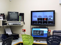
Photo 1
This photo shows the control room. From left to right the equipment comprises of the recording computer, lighting control console, sound mixing console, two computers for media and graphics in front of the patch panel, and the video switcher console and multi-view monitor.
The control room is acoustically isolated from the studio so the large window enables production personnel in the control room to see into the studio.
Sound from microphones and media sources is fed into a mixing console to produce the final program sound and this can be monitored via headphones or the pair of studio monitor loudspeakers that are mounted above the control room window.
Photo 2
A large multi-view monitor displays the video from each of up to eight video sources in small windows below the larger two preview and program windows. The preview window shows the video that is ready to be switched to the program output while the program window shows the current program output.
Below the multi-view monitor is a touch screen computer monitor that provides the control console for the video switcher. Touching a button activates its function and the button lights up accordingly, even in the appropriate colour. The traditional ‘T” bar that controls the video switching from preview to program also operates by sliding it up or down just like it does on a hardware based console.
Photo 3
Students are able to pre-record media content from school events such as sports days and cultural performances then incorporate this content into the TV program by loading it onto the media computers so it can be replayed into the video switcher on cue. Graphics can also be pre-produced and loaded into the video switcher. It’s even possible to incorporate historical VHS content via the VHS player.
The patch panel enables changes to the equipment configuration to be made quickly and easily to ensure maximum flexibility of studio use. The studio is designed so that it can be used for recording music as well as television.
Photo 4
The control room patch panel is divided into two distinct sections. The top half is for video while the bottom half is for data and audio.
At the very top is the video switcher. Short patch cables are used to connect the switcher inputs and outputs to the connectors for the various circuits that go to cameras and computers throughout the facility.
Each row of connectors on the patch panel corresponds to an identical panel of connectors in the studio area.
The video cabling is mainly SDI with some HDMI circuits also provided. The HDMI can be used for cameras but it is mainly used for monitors and computers as most of the HDMI cameras are converted to SDI using low cost video converters at the camera. This enables the school’s existing Handycams to be used with all the advantages of professional grade SDI standards. SDI also allows much longer cables than HDMI.
Professional grade balanced audio circuits are used throughout for studio microphones and other equipment. Most audio circuits are fitted with standard 3-pin XLR connectors. Some TRS jack circuits are also provided. Audio send circuits are provided to allow the use of fold-back monitors in the studio as well as the intercom system used by the production crew.
Data circuits are provided for DMX controlled lighting as well as Ethernet computer network connections.
Photo 5
This photo shows the news desk position with a roll-up chroma key background. A second roll-up chroma key background is provided on the left as well. These backgrounds can be rolled down and right across the floor as desired for any chroma key production work.
The cameras are on tripods fitted with dollies so they can be easily moved. The dollies have retractable feet to lock them to the floor once they are in position. This camera is focused onto the interview area on the right of the photo.
Photo 6
This photo shows the interview area. Like the cameras, the studio boom microphone is also mounted on a tripod and dolly for ease of use. Wireless lapel microphones are also provided for the presenters.
The camera on the right is focused on the news desk area. The monitors enable the presenters to see the outgoing program, essential when using chroma key techniques, and the text they are presenting teleprompter style.
Headsets for the production crew intercom system can be seen, one at the camera position and one at the boom microphone position.
Photo 7
This photo is taken from the news desk area looking toward the control room. The large white-board in the control room is used to plan the production process.
You may have noticed a mixture of red and white power outlets in these photos. This is done to clearly differentiate two separate power systems. The white outlets are for general purpose use while the red outlets are specially dedicated for sound and video equipment only. The red outlets in the studio and control room are all on the same circuit and are all controlled by a single master switch. This is done for both safety and technical reasons.
Photo 8
The studio ceiling is painted black to minimise light reflections and is fitted with a series of lighting bars to support the flood and spot lights that are used to light the presenters and chroma key backgrounds.
Four groups of three lighting circuits are provided for production lighting. In the control room, each circuit can be patched either into the lighting dimmer pack or a non-dim power point adjacent to the dimmers. This enables lighting to be easily configured for any production purpose. The system also provides a DMX and an Ethernet data circuit to each group of lighting circuits so digitally controlled equipment such as LED based lights can be used in the future.